EoC system in an old castle
AXING technology for multimedia reception
4th November 2016 | England is famous for its old castles and palaces. They mostly contain luxurious hotels, golf clubs or luxury spa hotels.

The company „Champneys “ operates four luxurious spa hotels in England. In order to meet today’s technical requirements, extensive modernization measures are currently underway, including the replacement of TV sets in the rooms. In addition to the DVB-T signals, the new TV system also requires a network connection in order to be able to control the devices centrally.
If you want to operate a modern communication system today, you can no longer avoid an IP distribution. However, the network connection or a LAN network does not exist in the rooms. The question arose how the signals come to the participant in existing objects? This question always arises for objects such as hospitals, hotels, airports, etc., which are subject to ongoing operations. The construction of a new infrastructure leads to operational restrictions and thus loss of revenue or immense costs for the renovation are caused.
Therefore, in this case, the AXING solution with EoC „Ethernet over Coax “ was chosen. With EoC technology, the coaxial infrastructure is used and a virtual infrastructure „LAN network “ is automatically obtained. All you have to do is have to have a passive return path available on the coaxial cable network, since the EoC signals are transmitted bidirectionally in the frequency range of 5 … 65 MHz. It may be necessary to replace the amplifiers. All other passive components only have to be able to transmit the return frequency range.
Certainly one could have used other technical solutions, but these solutions are not optimized for this application. Cable operators use DOCSIS technology, stable and reliable IP transmission in their networks. However, the costs for the CMTS are not negligible. For small objects, the cost per connection is quite high. With DOCSIS technology, a CMTS is installed at the source and the participants receive a cable modem. The max. Data rate in real operation today is approx. 400 Mbit / s. At the same time, it is a shared medium, i.e. all participants share the bandwidth and the cable network must be actively modernized for the rear. To do this, the amplifiers usually have to be replaced orin the rarest of cases, a return amplifier can be plugged in.
EoC technology
EoC development from AXING is based on an international standard IEEE 1901 and uses the lower frequency range of 2 … 68 MHz for the cable network, where there is very little attenuation in the coaxial cable. This means that routes up to 700 m in length can be bridged. Thanks to the OFDM modulation (Orthogonal FrequencyDivision Multiplexing), which is also used for DVB-T transmission, it is very insensitive to interference.
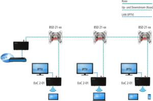
There are different operating modes of EoC technology. The operating mode „Peer-to-Peer “ is intended for home applications, the modems communicate with each other, so that the data for all modems is sent from every point. The operating mode „Master slave “ is intended for professional applications. Communication takes place from a master to the slaves and from the slaves to the master. It is not possible to communicate with each other, which helps to regulate data traffic. Figure 2 shows the typical structure of a master slaves system.
There are various EoC applications, such as the IP distribution in the private area, where end devices are to be connected to the Internet and there is only one antenna socket near the end device. The construction of the antenna distribution system is irrelevant, because it can be both SAT-ZF distributions or broadband distribution techniques. The topology of the distribution network is also irrelevant, it can be a tree network structure or star cabling.
The IP signals are fed into the distribution network via the modem at the antenna socket, at the transfer point or after the head point. Up to 64 modems can be connected in a network, whereby several networks can be implemented with intelligent clustering.
The data throughput is up to 500 Mbit / s (gross), which is approx. 230 Mbit / s (net). This means that several HD streams can be transmitted simultaneously. OoS can prioritize individual services and 128-bit AES encryption prevents unwanted users from entering.
Use in pure IP networks
The EoC devices can also be used in professional applications, so that they can be used in pure IP networks. In the typical IP structure, the switch is located at the source or on the meter. From there, the IP signals are routed to the slave devices via the coaxial network, to which the end devices are subsequently connected. In order to get to a new IP network via coaxial lines, the HF signals are switched off first, so that a new passive coaxial network is created. This means that no active components (amplifiers) are necessary.
At the central point where the amplifier was located, the IP signal is now connected by a switch to one or more EoC master modems. With the help of the clustering, smaller sub-networks are created so that the necessary data rate can be transferred. Figure 3 shows the change from a BK network to a pure IP network.
summary
Old coaxial cable systems can still be used for the most modern communication. With the help of EoC technology, coaxial cables have been given a second life. Due to the various possible applications, all versions of distribution networks can be used for this technology, regardless of whether satellite IF systems or BK systems in a construction network or star structure. The system can be used in the home network area as well as in professional applications in hotels, clinics, airports, etc. Subnets can be created using intelligent clustering, which means that the total number of end devices can be divided. Thanks to the two network connections per device, a further IP application is possible. Even with „bad “ connection, a „good “ transmission performance can still be achieved thanks to OFDM.Another version includes an integrated WiFi module in addition to the two network connections.